← Build · guide
The bench leaf
This guide builds the sensor node itself, the leaf, in the v0.5 build pictured here. A Grove thermistor feeds a Mayfly logger, which feeds your Pi. The Pi encrypts each reading with AES-256-GCM and hands it to the LoRa radio to queue for delivery, and a status LED blinks the whole time. This version lives in a waterproof case and runs off a USB battery bank, so it is portable enough to set out for a short field run, though without solar yet its runtime is whatever the battery holds. A leaf on its own senses, encrypts, and queues readings. It starts actually delivering them to a spreadsheet you own once you add a gateway, so this guide just gets the leaf working and proving itself, with no gateway required.
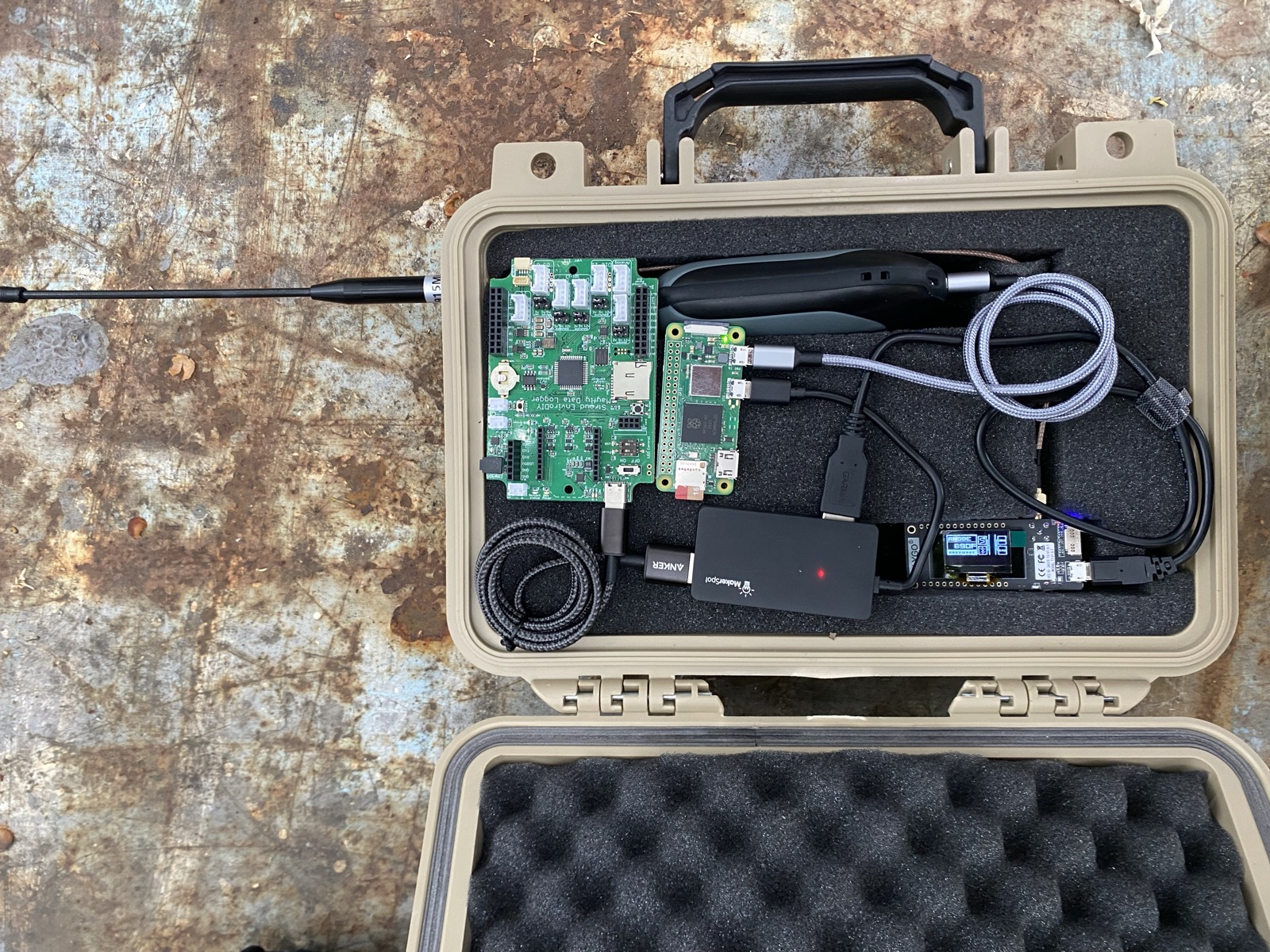
Parts
| Raspberry Pi Zero 2 W + 32 GB high-endurance microSD | $32 | the node's computer |
| USB power bank (a phone charging bank) | ~$20 | powers the node into PWR IN; a 5 V wall supply also works on the bench |
| Micro-USB OTG adapter | $3 | into the USB (data) port |
| 2-port USB 2.0 hub | $5 | bus-powered is fine on the 2.5 A supply |
| LILYGO TTGO LoRa32 v2.1 + 915 MHz antenna | $25 | the radio, never power it without the antenna |
| SMA male → SMA female bulkhead cable (RG316, ~20 cm) | $8 | panel-mounts the antenna |
| EnviroDIY Mayfly v1.1 | $80 | the sensor brain |
| USB-A → USB-C cable (short) | $4 | hub → Mayfly: power + serial |
| Seeed Grove Temperature Sensor v1.2 | $7 | NTC thermistor, zero wiring |
| Grove cable | $1 | usually ships with the sensor |
| LED + ~330 Ω resistor + breadboard + 2 jumpers | $3 | status LED on GPIO 17 |
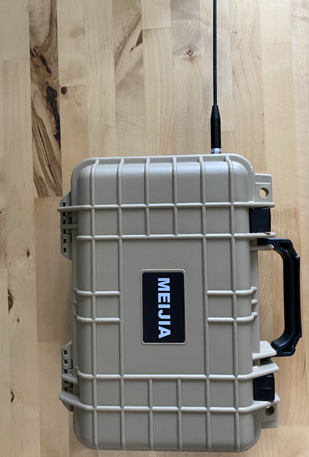
| Waterproof case (Pelican-style) + cable gland | ~$30 | weatherproof enclosure; the antenna mounts through the wall |
| Total | ~$218 |
Wiring
The Pi Zero 2 W has two micro-USB ports and only one carries data:
USB power bank ──► [PWR IN]   (power pins only, no data)

[USB] ── OTG adapter ── 2-port hub ──┬── TTGO LoRa32  → /dev/rnode
                                     └── Mayfly v1.1  → /dev/mayfly

GPIO 17 ── 330 Ω ── LED ── GND       (breadboard)

Mayfly AA0/AA1 Grove socket ── Grove cable ── Grove temp sensor
⚠ Never power the radio without its antenna attached. Transmitting into nothing can kill the TTGO. With the antenna on a bulkhead through the case wall, "attached" just becomes the case's resting state.
A note on connectors. LoRa boards normally use standard SMA (the board jack has a centre socket), not RP-SMA. RP-SMA looks identical in photos but won't mate. I checked in June 2026 that these boards are standard SMA, so order plain SMA.
Build steps
-
Flash the Mayfly
In the Arduino IDE, add the board package EnviroDIY ATmega Boards → EnviroDIY Mayfly 1284P and the Adafruit ADS1X15 library. Open the Grove-temp sketch, read its PORT CONFIG header, and upload. With the Grove sensor in the AA0/AA1 aux-analog socket (Grove power jumper at 3.3 V), the Serial Monitor at 115200 should show a
$MYC,…line every 10 s and the green LED blinking once per line. Thetemp_cvalue should be close to whatever your thermostat says. -
Set up the Pi
Flash Pi OS Lite 64-bit, clone the repo, run
leaf/setup.sh, and do the key andconfig.tomlsteps it prints. One of those is settingsensor = "mayfly"in/etc/mycelium-network-leaf/config.toml. Leavegateway_identity_hashblank for now. You'll set it when you build and pair a gateway. Then reboot. -
Plug the chain together
Wire it per the topology above, then check that both serial devices show up by running
ls -la /dev/rnode /dev/mayfly. (udev pins each device by chip, so hub port order never matters.) -
Start and watch
Run
sudo systemctl start rnsd leaf-node, thenjournalctl -u leaf-node -f. With no gateway yet, you should see the leaf sampling real readings and queuing them, with lines likesampled: temp_c=21.340 (queue depth 1)and the queue depth climbing. The LED slow-blinks discovering while it listens for a gateway to announce itself. That is the leaf working on its own.
Prove it's real
Pinch the thermistor between two fingers for a minute. In the journal,
the sampled temp_c should climb a few degrees. That is the
whole sense-and-encrypt path measuring an actual thing. Those queued
readings start landing in a spreadsheet you own once you add a gateway.
Troubleshooting
- No
/dev/mayfly: runlsusb. If the Mayfly's chip isn't10c4:ea60, adjust the udev rule inleaf/setup.sh. no valid MSAI line within 45s: the Mayfly is unpowered (check the hub), unflashed, or its cable is power-only. You can open the port by hand withpython3 -m serial.tools.miniterm /dev/mayfly 115200.- Readings but wrong temperature: the Grove power jumper is at 5 V while the math assumes 3.3 V, so flip the jumper.
What this proves, and what it doesn't
It proves the full encrypted pipeline end to end, the sensor-protocol contract across two independent implementations, named multi-parameter readings, and the whole reliability stack running under a real sensor.
It doesn't prove a season of real weather, solar power (this runs off a battery bank, so its uptime is just the battery), SDI-12, or a submersible water-temp probe. The waterproof case keeps the rain off, but the full field build, with solar, a real sonde, and a season of proof, is still ahead.